The Guide

The Gardner Denver GD150 Operating and Commissioning Checklist helps qualified installation and commissioning personnel verify that a GD150 compressor and its supporting system are correctly prepared before the unit enters service.

The checklist covers the conditions surrounding the compressor, including pipework cleanliness, mounting security, PTO status, engine management setup, test equipment, operating speed, inlet restriction, system leakage and pressure-relief valve operation.

These checks are intended to identify installation conditions that could prevent the complete system from operating as specified.

GD150 Operating and Commissioning Checklist Cover

Why GD150 Installation Verification Matters

A successful installation is not confirmed simply because the compressor starts.

The GD150 operates as part of a complete tank truck system that includes the PTO, engine controls, inlet and discharge pipework, test equipment, valves, silencer, pressure gauge and ancillary components.

Before commissioning begins, qualified personnel need to confirm that these elements are installed, secured and correctly sequenced.

Completing the installation checks before pressure is introduced gives commissioning personnel an opportunity to identify loose mountings, contaminated pipework, inlet restrictions, leakage and incorrectly configured components before the truck is placed into service.

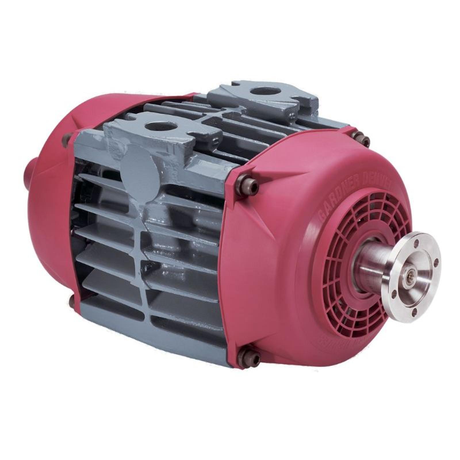
Product Photo Gd150 and gd175 V1

What Should Be Checked Before Commissioning a GD150?

The pre-operating inspection begins with the compressor’s supporting installation.

Installation area

Checklist requirement

Pipework

Clean flexible and welded pipe bores after fabrication

Flanges and fasteners

Confirm all flanges, fasteners and mountings are secure

PTO

Verify that the vehicle PTO is disengaged

Engine controls

Confirm the engine management system is set up correctly for the application

Ball valve

Open the ball valve if starting against tank pressure

Test equipment

Fit a 1.5 to 2-inch gate valve and silencer

Pressure monitoring

Fit a 0 to 43.5 PSI, or 0 to 3 bar g, discharge pressure gauge

Ancillary equipment

Confirm components are fitted and sequenced according to instructions

Each requirement should be verified before beginning the operating test. If a condition cannot be confirmed, it should be corrected before commissioning continues

Verify the GD150 Operating Speed and Inlet Condition

Once the installation checks are complete, confirm that the gate valve on the discharge pipework is open.

Engage the PTO according to the truck manufacturer’s instructions, slowly raise the clutch and adjust engine speed to drive the compressor at the operating speed required for the application.

The specified GD150 compressor input speed range is:

1,000 to 1,600 RPM

While the compressor is operating, check the inlet blockage indicator. The indicator should not show red. A red indication identifies a blocked filter or an inlet-pipework condition that requires investigation.

The inlet vacuum must not exceed:

0.7 PSI, or 50 mbar

These checks help verify that the compressor is operating within its specified speed range and that the inlet system is not placing excessive restriction on the unit. 

Check the GD150 Installation for Air Leaks

Installation integrity should be checked under operating conditions, not only during the initial visual inspection.

While the compressor is running, inspect the pipework for leaks. If leakage is found:

  1. Stop the machine.
  2. Tighten the applicable fasteners.
  3. Recheck the system before continuing.

Next, partially close the gate valve to raise discharge pressure to 3 PSI, or 0.2 bar, below the relief valve’s full-bypass setting. The full-bypass setting is stamped on the relief valve.

Inspect the system again for leakage at this pressure. If corrective work is required, stop the machine and secure the affected fasteners before resuming the test.

If the system is operating correctly, continue running the compressor until the total test time reaches 30 minutes, then check again for air leaks.

Verify the GD150 Relief Valve Installation and Operation

The pressure-relief valve must be tested as part of commissioning.

Slowly increase pressure beyond the setting stamped on the valve until the relief valve operates.

Relief valve test point

Acceptance requirement

Valve begins to crack

Within 10% below the set pressure

Leakage before cracking

Slight leakage permitted up to 7 PSI, or 0.5 bar g, below set pressure

Full opening or bypass

Within 5% of the set pressure

Valve reseating

Before pressure falls 7 PSI, or 0.5 bar g, below full-bypass pressure

After the valve reaches full bypass, slowly reduce pressure and confirm that it reseats within the specified range.

Complete the operating inspection by verifying that all fastenings remain tight and that the flanges are leak-free.

GD150 Operating Limits to Confirm During Commissioning

Qualified personnel should know the compressor’s operating limits before beginning the test.

Operating condition

GD150 limit

Compressor input speed

1,000 to 1,600 RPM

Maximum inlet vacuum

0.7 PSI, or 50 mbar

Maximum discharge pressure

36 PSI, or 2.5 bar g

Total test time

30 minutes

Pipework will become hot during testing and operation. Personnel should follow the applicable safety requirements throughout the procedure.

The compressor must never be started against a pressurized tank or discharge line.

Complete the Commissioning Test Safely

After the installation and pressure-protection checks have been completed:

  1. Return the engine speed to idle.
  2. Disengage the PTO.
  3. Stop the engine.
  4. Remove the test apparatus.
  5. Disconnect the discharge hose.
  6. Fit a blanking cap.

The installation should not be considered ready for service unless the required checks have been completed, the relief valve has operated within the documented limits, all fastenings remain secure and the flanges are leak-free.

Country

Your request will be forwarded to the relevant individuals to assist with your request.
By clicking 'Send' you are authorizing Gardner Denver to contact you so that we may fulfill your request, as well as to communicate with you regarding our products and services.
Terms and Conditions
Privacy Policy

(* required fields)

This site is protected by reCAPTCHA.

Frequently Asked Questions

Confirm that the flexible and welded pipe bores are clean, flanges and mountings are secure, the PTO is disengaged, engine management is correctly configured, the required gate valve, silencer and pressure gauge are installed, and ancillary components are correctly fitted and sequenced.

Reach Out to Us