
Troubleshooting Pneumatic Conveying Systems: Practical Diagnostics for Steady, Reliable Performance

Unplanned downtime affects throughput, and pneumatic conveying troubleshooting often starts with recurring symptoms: line plugs, low capacity, unstable dilute‑phase flow, high wear, or inconsistent material feed. Most conveying problems trace back to four areas: the line charger, gas volume, conveying pressure, or the product receiver. This guide gives maintenance teams, operators, and engineers a direct process to identify the source of instability and restore reliable conveying performance. 


Download the White Paper

Troubleshooting Pneumatic Conveying Systems: A Practical Guide

Download the full PDF for step‑by‑step diagnostics covering material feed issues, blower and airflow troubleshooting, gas‑pressure checks, and receiver‑related failures.
Troubleshooting Pneumatic Conveying System White Paper Cover.png

Country

Your request will be forwarded to the relevant individuals to assist with your request.
By clicking 'Send' you are authorizing Gardner Denver to contact you so that we may fulfill your request, as well as to communicate with you regarding our products and services.
Terms and Conditions
Privacy Policy

(* required fields)

This site is protected by reCAPTCHA.

What This Guide Covers

1. Conditions Required for Stable Dilute‑Phase Pneumatic Conveying 

A pneumatic conveying system runs effectively only when four conditions align: 

  • The material behaves properly in dilute‑phase flow
  • The line charger introduces material at the correct rate
  • Gas volume and pressure are sufficient for the conveying distance
  • The receiver separates gas and solids without restriction

Incorrect conveying mode is a frequent root cause. If the system’s mode does not match how the material wants to behave in motion, troubleshooting attempts downstream won’t solve the underlying issue. 


2. Diagnosing Material Feed Problems  

Most pneumatic conveying system problems begin at the line charger or rotary airlock. The white paper outlines common issues: 

  • Low rotary airlock capacity based on speed or material density
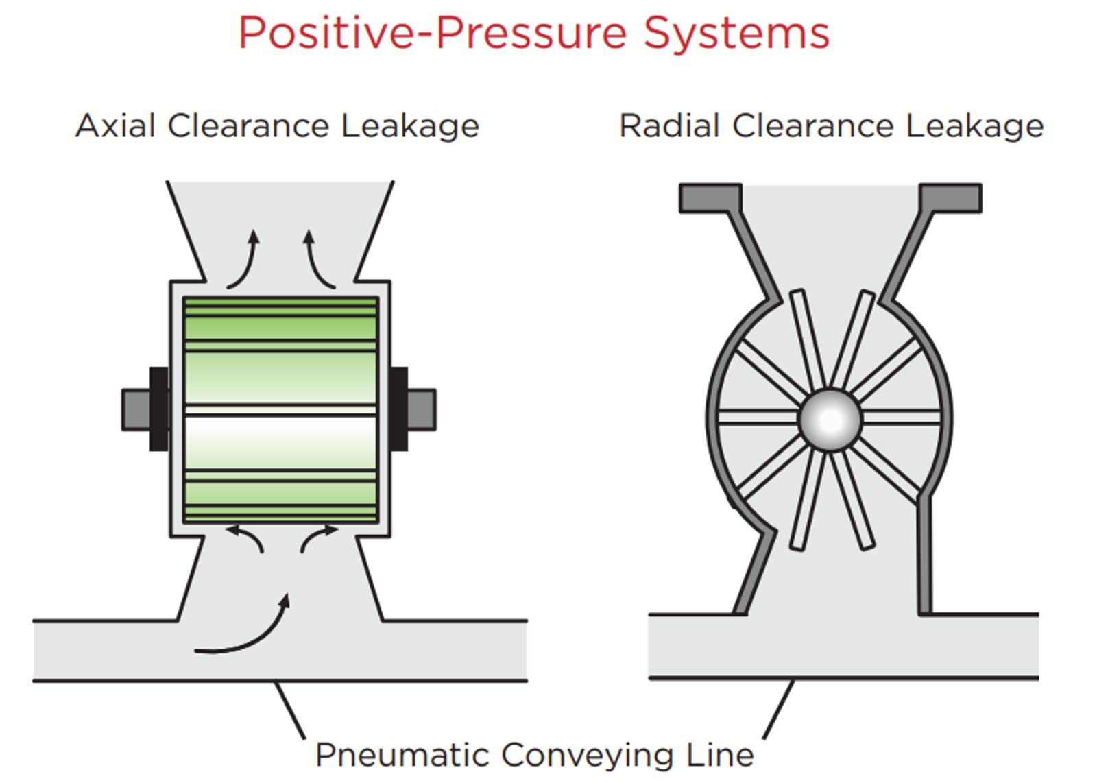
  • Air leakage from rotor clearance or differential pressure
  • Limited venting for fine materials
  • Rotor design mismatched to the product
  • Upstream flow restrictions including bridging or blockage

These checks help determine whether the system faces a feed‑rate deficit, inconsistent density, or a mechanical limitation before adjusting blower settings. 

3. Diagnosing Gas‑Volume Problems 

Gas volume issues appear in two ways: too little air to carry the material, or too much air causing high velocities, product degradation, or energy waste.

Typical contributors include:

  • Leaks at the line charger or pipe connections
  • Diverter valves not sealing
  • Incorrect material‑to‑gas ratio
  • Changes in material characteristics
  • Gas‑mover performance changes

The white paper includes a diagram of a conveying-system characteristic curve showing how capacity shifts with gas-volume adjustments.

Pneumatic Conveying Line Diagram

4. Restoring Adequate Conveying Pressure

Pressure loss usually points to:

  • Blocked gas‑mover inlet
  • Partially moved diverter valves
  • Overfeeding at the line charger
  • Backpressure from the dust collector or receiving vessel

The included pressure‑loss checklist helps teams isolate where resistance has increased and what component is restricting the line.


5. Transport Line Failure Modes

Line plugs usually follow predictable patterns:

  • Plugs in the first 50 feet often indicate low air volume
  • Plugs farther downstream suggest layout issues, leakage, slopes, or consecutive bends
  • Low capacity may result from excessive turns, vertical rises, or long equivalent line length

The guide also covers wear mechanics and explains how velocity, raised to the power of 3 to 5, accelerates pipe erosion.


6. Troubleshooting the Product Receiver

Receiver problems show up as:

  • High pressure differential
  • Incorrect air‑to‑cloth ratio
  • Filtration media not suitable for the product
  • Material buildup in the hopper
  • Discharge rotary airlock leakage

The guide provides strategies to increase separation efficiency, reduce erosion at inlets, adjust receiver geometry, and maintain stable flow.

Who This Guide Helps

This resource supports: 

  • Maintenance and reliability teams monitoring blower and line performance
  • Process and project engineers responsible for dilute‑phase conveying system design
  • Operators addressing chronic line plugs, low capacity, or product degradation
  • Facilities evaluating airflow adjustments for energy reduction

FAQs

Compare system behavior with the material’s physical characteristics. If the mode doesn’t match how the product behaves in motion, small disturbances create chronic instability, including line plugs and inconsistent flow. 

Reach Out to Us

Find a Distributor